
OMOGANEYA Technical Academy 〜 OMOGANEYA Technical School 〜
Fundamentals of Electrical Engineering | Chapter 1: Direct Current (DC) Circuits – 1.10 Kirchhoff’s Laws
1.10.1 Kirchhoff’s Laws
Building on Ohm’s law, Gustav Robert Kirchhoff systematized Kirchhoff’s laws in a form that can be applied to more general circuit networks.
Kirchhoff’s laws consist of the first law (Kirchhoff’s current law), which focuses on current, and the second law (Kirchhoff’s voltage law), which focuses on voltage.
Kirchhoff’s laws are essential for analyzing complex circuit networks and are known as fundamental laws of electric circuits.
1.10.2 First Law (KCL: Kirchhoff’s Current Law)
At any junction in a circuit network,
the sum of the currents flowing in is equal to the sum of the currents flowing out.
In other words,
the algebraic sum of the currents flowing into any junction is zero.
*Based on the law of conservation of charge
Therefore, the following equations hold for Figure 1.10-1.
In general, this is expressed as follows.
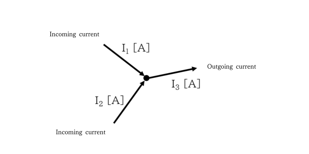
Figure 1.10-1 Kirchhoff’s Current Law
1.10.3 Second Law (KVL: Kirchhoff’s Voltage Law)
When going around any closed loop in a circuit network,
the algebraic sum of the electromotive forces and the voltages across each part is zero.
In other words,
for any closed loop in a circuit network, the sum of the potential changes around the loop is equal to the sum of the electromotive forces in that loop.
*Based on the law of conservation of energy
Let us now write equations for the circuit in Figure 1.10-2 based on Kirchhoff’s second law.
Going around closed loop ① in the direction of the red arrow (clockwise), and taking voltage rises as positive and voltage drops as negative, the following equations hold.
In general, this is expressed by the following equation.
In practice, however, the following equation is often used.

Figure 1.10-2 Kirchhoff’s Voltage Law 1
As explained above, Kirchhoff’s law holds for any closed loop, so closed loop ② in Figure 1.10-3 can be treated in the same way.

Figure 1.10-3 Kirchhoff’s Voltage Law 2
Let us consider one more case.
Figure 1.10-4 shows closed loop ③, chosen so that it does not pass through the middle resistor R2.
In this case, the following equations hold.

Figure 1.10-4 Kirchhoff’s Voltage Law 3
Note that the three loop equations are not independent of one another;
Eq. (1.10-11) can be obtained by adding or subtracting Eq. (1.10-4) and Eq. (1.10-8).
When there are three unknown currents, they can be found by combining KCL with two independent KVL equations.
About This Article
References
- Denki Kiso (Jo) [Fundamentals of Electricity, Vol. 1], Corona Publishing, Toshio Utsunomiya, Hiroshi Takahashi, Isao Izumi
- Denki Kairo Tekisuto [Electric Circuit Textbook], Nippon Riko Shuppankai, Koichiro Seya
*This article was compiled based on the author’s understanding, with reference to the above literature.

Written by
- Company
- Marine Techno Services, Ltd.
- Business
- ・Import and export of marine machinery and equipment
・Renewable energy-related services
・Procurement and sale of industrial equipment and products - URL
- https://marinetechno.jp/
- Contact
- info@marinetechno.jp
Contact Us
contactFeel free to contact us about listing your products or services, questions on existing listings, or procurement, sales, and trade support through OMOGANEYA.