
OMOGANEYA Technical Academy 〜 OMOGANEYA Technical School 〜
Fundamentals of Electrical Engineering | Chapter 1: Direct Current (DC) Circuits 1.6 Series Connection of Resistors and Voltage Division
Practical electric circuits are often constructed using multiple connected resistors.
This section explains how to calculate the equivalent resistance when multiple resistors are connected in series.
1.6.1 Series-Connected Resistors, Equivalent Resistance, and Equivalent Circuits
A circuit in which resistors R1 and R2 [Ω] are connected in series, as shown in Figure 1.6-1, is called a series circuit.

Figure 1.6-1 Series Circuit
When a voltage E [V] is applied between points a and b in this series circuit, the voltages V1 and V2 [V] across the respective resistors can be calculated using the following equations.
The voltage V across the entire circuit is calculated using the following equation.
If R1 + R2 = R [Ω], then
Therefore, R1 + R2 can be combined and replaced by a single resistance R.
This is called the equivalent resistance. For a series circuit containing n resistors, the equivalent resistance is expressed by the following equation.
Based on the above, the circuit shown in Figure 1.6-1 can also be represented as shown in Figure 1.6-2 below.
This is called an equivalent circuit, meaning a simplified representation of the original circuit that retains or approximates its electrical characteristics.
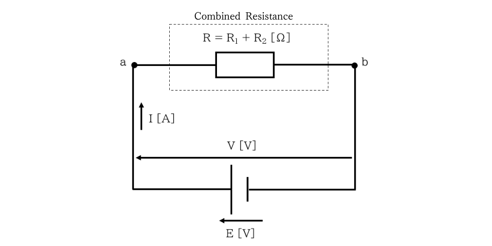
Figure 1.6-2 Equivalent Circuit of a Series Circuit
【Note】
The circuit diagram contains the two symbols E [V] and V [V].
E [V] represents the electromotive force of the power source—its ideal source voltage—while V [V] represents the voltage actually applied to the circuit when the power source is connected, known as the terminal voltage.
Because a practical power source has internal resistance, a voltage drop occurs across this internal resistance when load current flows. Therefore, E [V] ≠ V [V] in general.
However, when an ideal power source with negligible internal resistance is assumed, the electromotive force and terminal voltage are treated as equal, so E [V] = V [V].
In this chapter, the source voltage and the voltage applied to the circuit are represented separately to clarify the concept of a power source.
1.6.2 Voltage Division by Resistors
In Figure 1.6-1, the voltages V1 and V2 [V] across resistors R1 and R2 [Ω] are given by Ohm’s law as follows.
From Equation (1.6-4), I = V / R [A]. Substituting this into Equations (1.6-6) and (1.6-7) gives the following results.
Equations (1.6-8) and (1.6-9) show that the applied voltage is divided among the resistors in proportion to their resistance values.
In a series circuit, the voltage is divided among the resistors, and the voltage across each resistor is proportional to its resistance.
This is called the voltage divider rule and is used in a voltage divider circuit to reduce a voltage by a specified ratio.
In a circuit containing n resistors connected in series, the voltage Vi [V] across the i-th resistor Ri [Ω] is expressed as follows.
About This Article
Reference
・Fundamentals of Electricity, Volume I, Corona Publishing Co., Ltd., by Toshio Utsunomiya, Hiroshi Takahashi, and Isao Izumi
※This article was prepared with reference to the source listed above and organized based on the author’s understanding.

Written by
- Company
- Marine Techno Services, Ltd.
- Business
- ・Import and export of marine machinery and equipment
・Renewable energy-related services
・Procurement and sale of industrial equipment and products - URL
- https://marinetechno.jp/
- Contact
- info@marinetechno.jp
Contact Us
contactFeel free to contact us about listing your products or services, questions on existing listings, or procurement, sales, and trade support through OMOGANEYA.